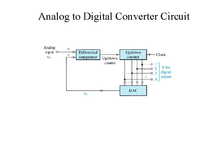
Understanding AD An Analog to digital converter Circuit Diagram divisions or units of the full analog range. Hence, 1/2 LSB represents an analog quantity equal to one half of the analog resolution. The resolution of an ADC is usually expressed as the number of bits in its digital output code. For example, an ADC with an n-bit resolution has 2n possible digital codes which define 2n step levels. However
One way to analyze and understand how this circuit works is to replace the R/2R ladder with its Thévenin equivalent circuit, then treat it as an inverting amplifier. Digital to Analog Converter Performance Specs. Several factors affect the performance of a DAC. Here are a few of the major ones to watch out for.
Digital to analog conversion Circuit Diagram
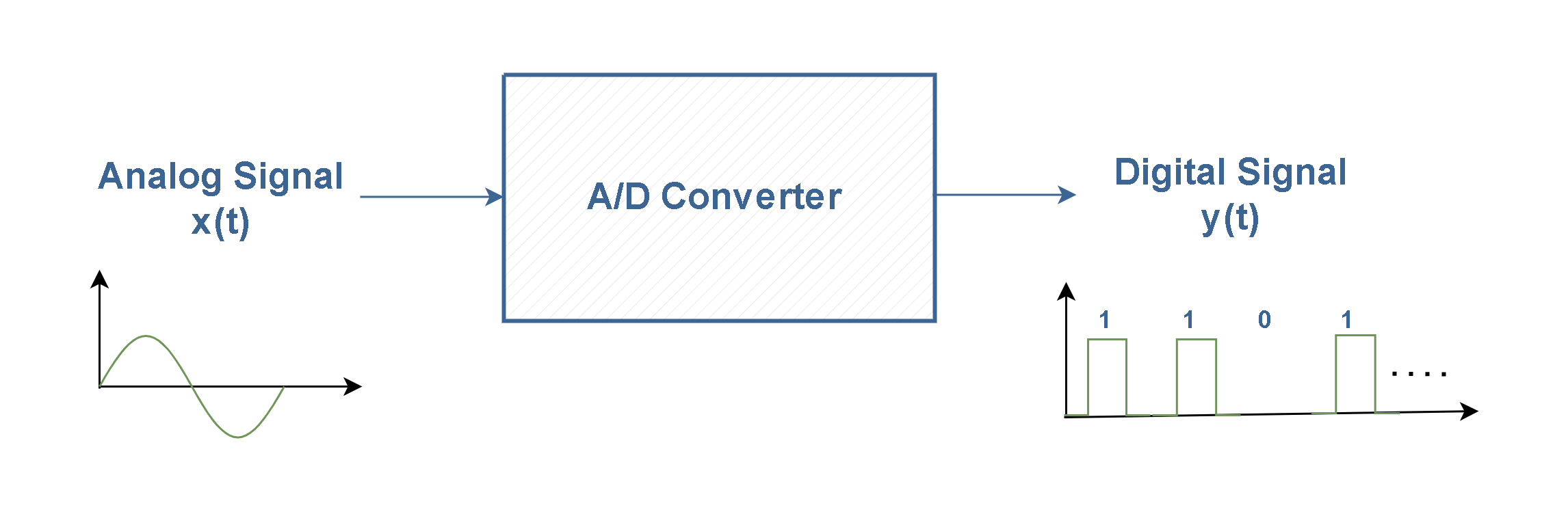
Digital-to-analog (DAC) converter circuits are an important component in many of today's technologies, converting digital signals into analog signals. A DAC circuit diagram is a graphical representation of how these components are connected in order to create an effective DAC system. The DtoA models a digital-to-analog converter with several types of distortion. The input to the model is a digital word in integer form, while the output is a quantized real baseband signal. At every execution of this model, 1 sample is read from the input and RepeatOutput samples are written to the output. We just need a way to provide the required integer input. This technical overview In digital circuits the voltage signal is in two forms, either as a logic high or logic low logic levels, which represent binary values of 1 or 0. In a analog to digital converters (ADC), the input analog signal is represented as a digital magnitude, while a digital-analog converter (DAC) converts the digital magnitude back to an analog signal.
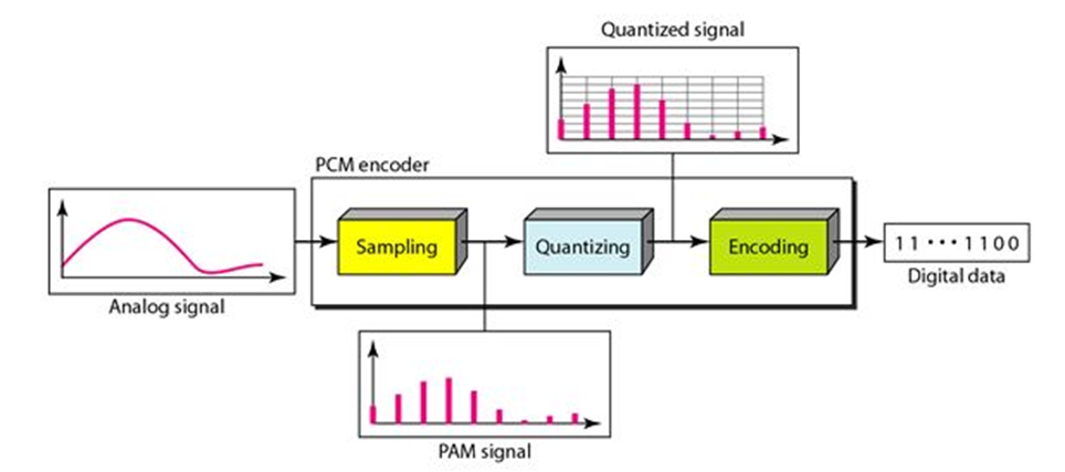
![The process of analog-to-digital conversion [4]. Circuit Diagram](https://www.researchgate.net/publication/376290710/figure/fig1/AS:11431281210040434@1701962200281/The-process-of-analog-to-digital-conversion-4.png)
The process of conversion of a digital input signal (1s and 0s) into an analog output signal is called digital to analog conversion (D/A). The digital signal usually encoded using a binary code consisting of 0s and 1s. In electronics, the circuits and systems which help in converting the binary code into analog signals are called digital to Here is a circuit schematic for a pulse-width modulated DAC. Here the counter is used to produce a count value A that ramps up linearly in a sawtooth manner. The digital value we want to convert to analogue value is data_in, which is stored as B in the input register. A digital comparator circuit compares this input data with the counter value
Digital to Analog Conversion Circuit Diagram
What is DAC (Digital to Analog Converter)? Digital to analog converter is an electronic circuit that converts any digital signal (such as binary signal) into an analog signal (voltage or current). The digital signal such as the binary signal exist in the form of bits & it is the combination of 1's & 0's (or High & low voltage levels).