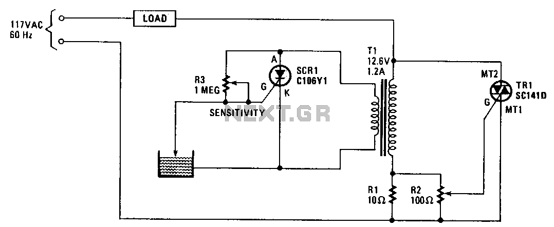
Songs of the Swamp Circuit Diagram The less water the sensor is immersed in, the poorer the conductivity and the higher the resistance. The sensor generates an output voltage proportional to the resistance; by measuring this voltage, the water level can be determined. Water Level Sensor Pinout. The water level sensor is extremely simple to use and only requires three pins to I need water level circuit. 1. Tank low, mid, high indication. 2. Sump/ground Tank low/ high indication. 3. CD-4001, 4093, 4017 IC. 4. Dry run indication. 5. Input sensor opto-coupler type. 6. Preferably low DC sensing voltage I have a water level sensor which gives me an output of 0-190ohm. It is connected to a gauge at 12V. This is a tutorial to build a simple water level indicator alarm circuit using transistors. It indicates different levels of water and raise an alarm upon getting the tank full. Sensors and Transducers Semiconductors Test Products Tools Projects 555 Timer Circuits Op-amp Circuits Audio Circuits Power Supply Circuits VLSI Projects All
Generally, water stored in overhead tank is wasted due to over flow ,when the tank is full. Water level alarm using micro-controllers like 8051 and AVR are shown in previous articles.This article shows simple circuits of water level indicator with alarm.. Three circuits were shown here are simple and built using transistors, 555 timer and ULN2003 IC.
Water Level Alert using Float Sensor & 555 Timer Circuit Diagram
Overview. This article explores a water level alert circuit using a 555 timer and a float sensor, designed to detect and signal when water reaches a predefined level. The NE555 timer IC is a versatile and cost-effective solution for creating automated alert systems.This project is ideal for applications like water tanks, reservoirs, or flood detection systems.

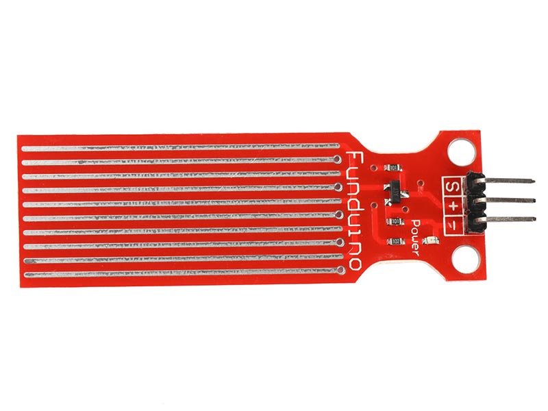
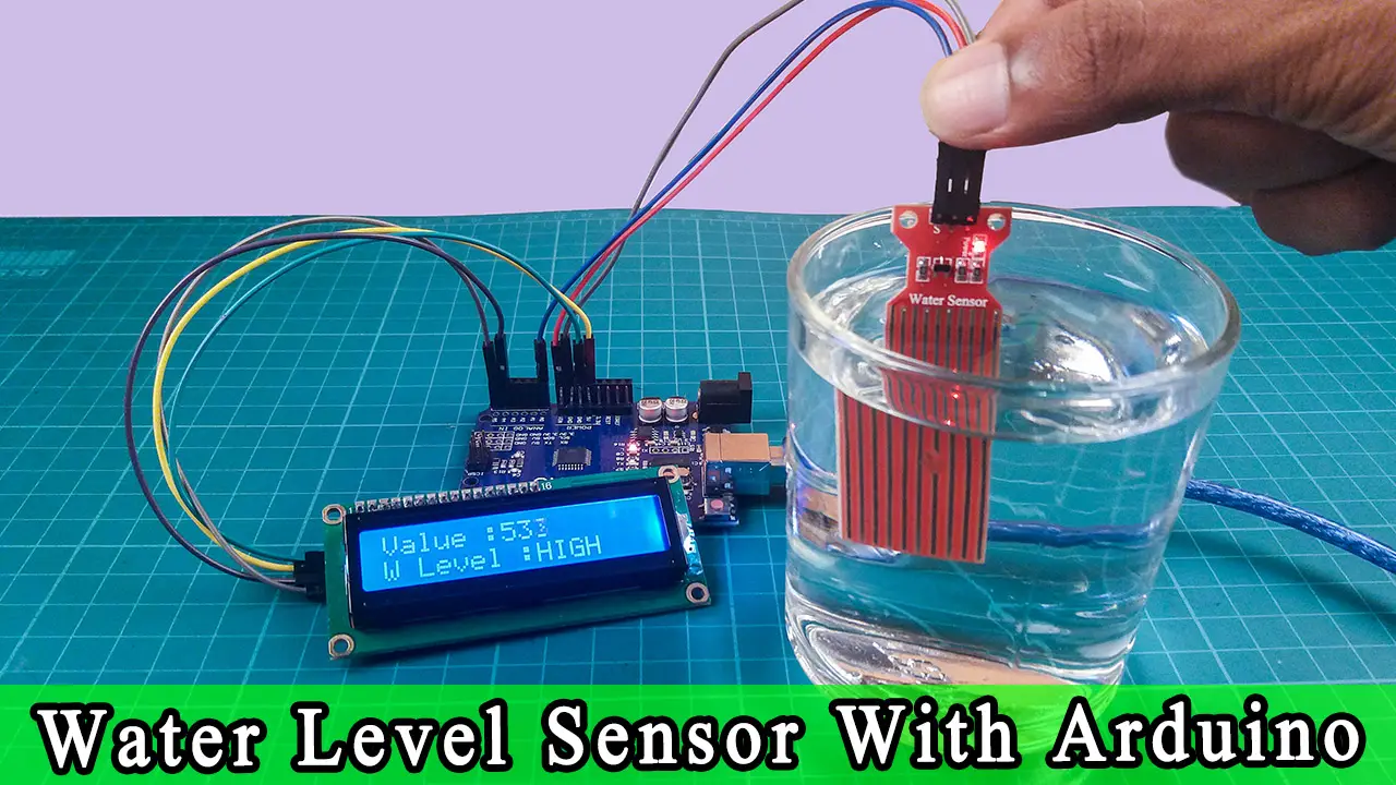
Learn how to use the water sensor with Arduino, how to detect the water leakage, rainfall, tank overflow, how to measure the water level, how to calibrate the water sensor, how water sensor works, how to connect water sensor to Arduino, how to code for water sensor using Arduino, how to program Arduino step by step. The detail instruction, code, wiring diagram, video tutorial, line-by-line
Simple Water Level Indicator with Alarm (Tested Circuits) Circuit Diagram
A water level sensor detects the presence or level of water by measuring changes in conductivity. It typically consists of a set of exposed conductive traces that act as probes. When water bridges the gaps between the traces, the sensor produces an electrical signal indicating water presence or level.
