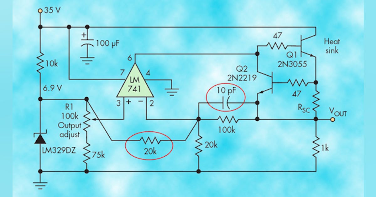
Pauls DIY electronics blog My New Power Supply Design Project Part 3 Circuit Diagram As the name defines, a transformerless power supply circuit provides a low DC from the mains high voltage AC, without using any form of transformer or inductor. It works by using a high voltage capacitor to drop the mains AC current to the required lower level which may be suitable for the connected electronic circuit or load. An in-depth guide to power supply design. Explore the build or buy decision, the different topologies, design requirements and power supply standards. Electronics-based products and applications generally operate on low voltage DC supplies. For products designed to work from mains power, the power supply must convert from AC mains to a DC However, for achieving a regulated dual power supply with the desired level of dual voltage at the output is something which normally requires a complex design using costly ICs. The following design shows how simply and discretely a dual power supply could be configured using a few BJTs, and a few resistors.
In PCB design, low voltage power supply refers to the power circuitry that generates the required voltage for the components. This often included voltage nodes of 5V, 3.3V or 1.8V that power the underlying circuitry. A low voltage power supply takes on the incoming voltage and converts it to the desired value. A power supply is often separated

Considerations In Designing Single Supply, Low Circuit Diagram
By changing resistor R2 for a 2k ohm potentiometer we can control the output voltage range of our PSU bench power supply from about 1.25 volts to a maximum output voltage of 10.75 (12-1.25) volts. Then our final modified variable power supply circuit is shown below. Variable Voltage Power Supply Circuit In the realm of low voltage power supply design, understanding the intricacies of power converter topologies is essential. The design process must focus on optimizing both the voltage conversion ratio and power conversion efficiency, which are critical for meeting the demands of modern electronic applications.

Figure 1. A linear regulator converts one voltage into another. For many years, a typical power converter consisted of a 50 Hz or 60 Hz transformer, connected to the power grid, with a certain windings ratio to generate a nonregulated output voltage, a few volts higher than the needed supply voltage in a system. Comparing 5 V with V of supply voltage, used as a reference: 2exp(n) 5 V 3 V . 2exp(-12) 1.22 µV 732 µV. 2exp(-16) 76 µV 46 µV. Voltage regulator devices, such as the REF19x series, are useful in stabilizing supply or reference voltage. They will maintain their output voltage at a constant level until the regulator reaches its "drop-out
