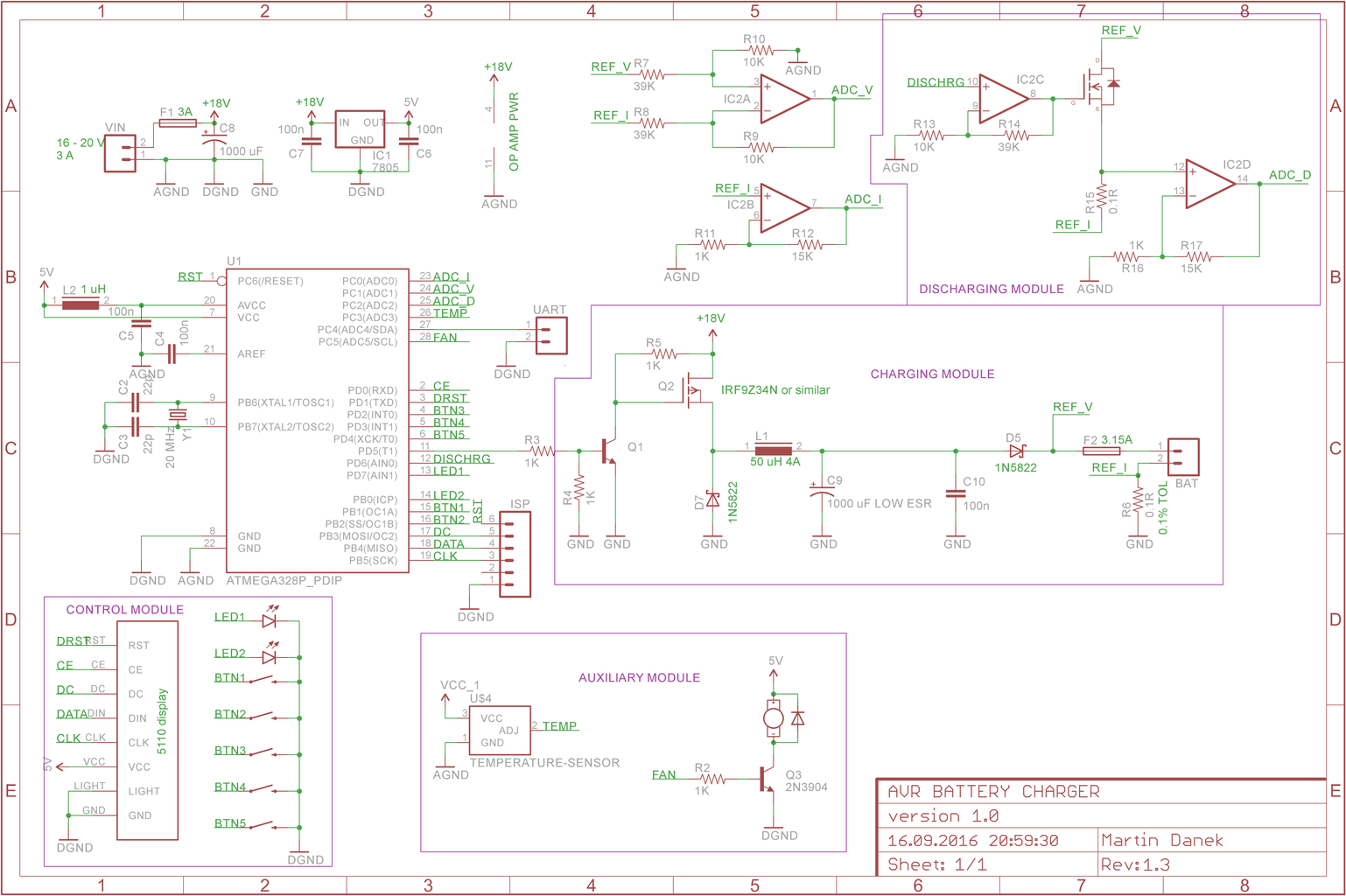
How to Make Universal Battery Charger 4 Steps with Pictures Circuit Diagram This 12-battery charger circuit provides an Automatic cut-off facility when the battery gets fully charged. Before the use of this circuit, you need to adjust the Cut off-voltage range for the auto cut. This adjustment is done by the moving 10k preset and for testing of output voltage auto cut range, a multimeter is connected to the output

Now lets see how the entire battery charger design may look including the constant voltage/current set up along with the above cut-off configuration: So here's the completed customized battery charger circuit which can be used for charging any desired battery after setting it up as explained in our entire tutorial: The opamp can be a IC 741 How to Make Lipo Battery Charger Circuit: In this project, we are going to make a simple lipo battery charger using TP4056 module with battery protection. The circuit that charges the battery by supplying the charge carrier (i.e-electrons) to it is battery charger circuit. Most of… In this video, we're going to learn how to make a battery charger control circuit. This is a fun project that you can do to learn some basic electronics skil

Constant Current Battery Charger Circuits Circuit Diagram
It gives you all the information you need to make a high-quality battery charger from scratch. So, get ready to learn valuable insights on building your constant-current battery charger circuit and take a step towards becoming a self-sufficient electronics pro! Circuit 1: Single Resistor Method Yes, building a circuit for a homemade battery charger is a relatively simple process. You will need to obtain a few basic components such as a transformer, diodes, capacitors, and resistors. Once you have these components, you can follow a step-by-step guide to create a circuit that will charge your battery.

In this video, we demonstrate how to build aIn this video, we demonstrate how to build a simple yet effective 12V battery charger circuit with an automatic c The above circuit diagram is a lead-acid battery charger schematic. The main component of the circuit is the LM317 IC. The circuit gives the desired voltage to charge the 12V fixed lead-acid batteries or 12V SLA batteries. The charging current can be changed with a 1K potentiometer. 12V Battery Charger Circuit Useful Steps. Follow the steps on how to make a 12V Battery charger. 1) Make a Bridge rectifier by connecting 4 1N4007 Diodes in the following configuration. 2) Solder the +ve & -ve Terminals of the bridge rectifier to the secondary winding of the Non-C.T Transformer. 3) Trim excess leads of the bridge rectifier.
