Digital Stethoscope Circuit Diagram Datasheet So without further ado let's get started. How Does Wireless Digital Stethoscope Work? Before we go any further in the article, let's discuss how this circuit works. In order to get the heartbeat data, we will first get a stethoscope and cut it in half to fit a condenser microphone, so that we could get the heartbeat sound from the stethoscope.

The circuit diagram of the proposed electronic stethoscope amplifier is designed using two stages, one consisting of the opamp based tone control circuit, and the integrated proper amplifier stage.
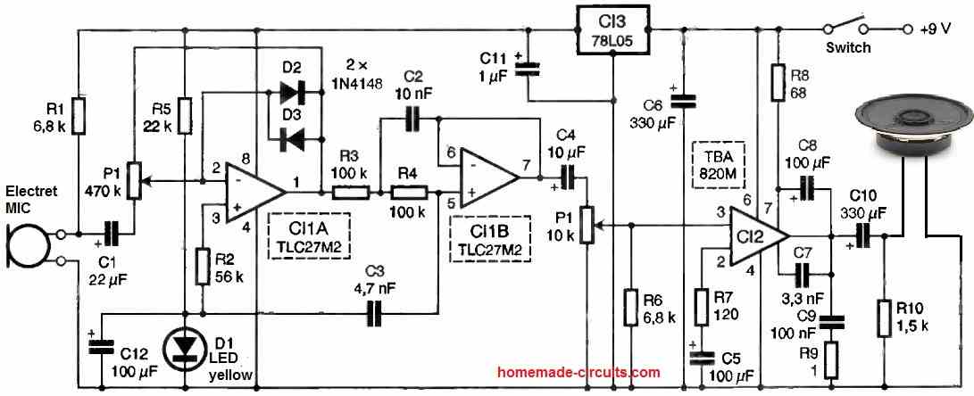
electronic stethoscope Circuit Diagram
The DIY Wireless Digital Stethoscope project aims to create a modern stethoscope using wireless communication and digital signal processing. This project allows for remote monitoring of heart and lung sounds, offering medical professionals an enhanced tool for diagnosis and patient care.

For the MIC, we use the popular electret MIC, which is the recommended device for all microphone based circuit applications. For the amplifier, we use a standard IC LM386 based amplifier circuit. The entire circuit of the bluetooth stethoscope transmitter circuit is shown below: Parts List Resistors 1/4 watt 5% 4k7 = 1 100 ohm = 1 10 ohm = 1 Hello, i am making an electronic stethoscope. But iam facing several problems in it. I am using CM-01B Piezoelectric sensor . Here are the components of my circuit below. My circuit: 1) Charge amplifier using INA128P 2) Voltage amplifier using A620AN 3) BANDPASS Filter using TLC2272CP 4) LM386

Digital Stethoscope Circuit Diagram
In this video you have seen about the digital stethoscope and how to build your own digital stethoscope.And I also explained what are the components required
